EE 230 Final Lab Project
Infrared Transmitter
Infrared Transmitter
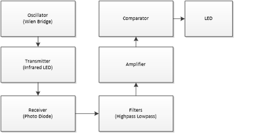
The goal of this project was to use operational amplifiers
to generate and transmit a signal which can be chosen from two signals selected by a switch. The signal is then
transmitted through the use of an infrared LED to a photo diode which acts as
the receiver. The signal was then be filtered and amplified to light a red LED
(For a 1kHz signal) and a green LED (for a 10kHz signal).
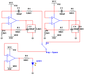
To the right is an image of the circuit diagram for our oscillators and transmitter. We used Wein-bridge oscillators as our waveform generators for the signal.
To the right is an image of the circuit diagram for our oscillators and transmitter. We used Wein-bridge oscillators as our waveform generators for the signal.
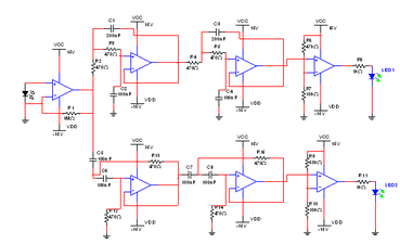
This is an image of our circuit diagram for our receiver and filters to light our LED's. On the left you can see the photo diode which picks up the signal transmitted and is amplified by an op-amp amplifier circuit. On the upper side of the diagram, we have the fourth
order Sallen Key lowpass filter and amplifier to light the LED 1 at frequencies below 2KHz. on the lower side of the diagram we see our fourth
order Sallen Key highpass filter and amplifier to light the LED 2 at frequencies higher than 5KHz.
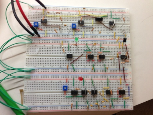
In the end this is what our project looked like. It may not be seen as beautiful to most people but it absolutely is to me and my lab partner. Especially because it works.
