Triangle Rendering Engine Project
IntroThis project was given to my and my partner(Cory Snooks) for our EE 465 lab. The objective was to attempt an IC design contest held by Chip Implementation Center (CIC) in Taiwan. The specific objective for the Cell-based IC category of this contest was to generate a Triangle Rendering Engine.
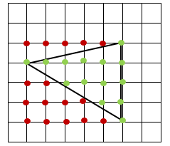
Basic ConceptThe basic idea of this project is to generate an HDL module which will take in three points denoted by three bit numbers x and y and determine all points inside the triangle made by those three points. There are a few assumptions that are given in the contest specifications to make the design simpler such as the fact that one of the faces of the triangle is always perfectly vertical and the order of points input is always from bottom to top. The specifications of the project can be seen below in the contest preliminary.
|
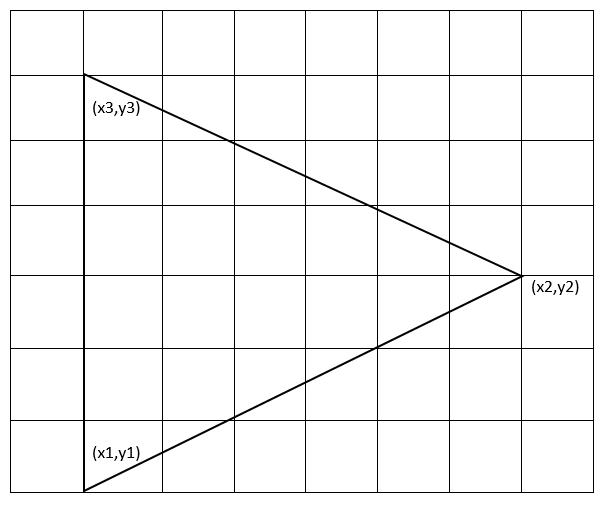
Example of triangle input
|
Design Methodology
From the hint given in the project specifications, the equation to determine if a point on a line is as follows:
(x-x_1)/(y-y_1 )-(x_2-x_1)/(y_2-y_1 )=0
If the point is to the right hand side of the line, this equation is true:
(x-x_1)/(y-y_1 )-(x_2-x_1)/(y_2-y_1 )>0
If the point is to the left hand side of the line, this equation is true:
(x-x_1)/(y-y_1 )-(x_2-x_1)/(y_2-y_1 )<0
For our design we will use a modification of these equations in order to accurately determine if a coordinate was located in the triangle. The direction of the triangle had to be found by comparing the value of x_1 to x_2 in order to determine which metric to compare the equation to. If x_1 < x_2 then the triangle is right facing and if x_1 > x_2 then the triangle is left facing.
To compute whether a point of interest is inside the triangle, we will be using the following assumptions:
y_1 =y_3
y_1 1 < y_2< y_3
Manipulating the equation (x-x_1)/(y-y_1 )-(x_2-x_1)/(y_2-y_1 )=0 , we can derive the equation:
(x-x_1)/(y-y_1 )=(x_2-x_1)/(y_2-y_1 ) → (x-x_1 )(y_2-y_1 )-(x_2-x_1 )(y-y_1)
To do all these computations in one clock cycle, we would need 2 multipliers and 5 adders. To implement sharing of these blocks, we will do these computations in multiple clock cycles. For our design, we used the following variables to represent parts of the equation:
(x-x_1 ) or (x-x_3 )=A
(y-y_1 ) or (y-y_3 )=B
(x_2-x_1 )=C0
(y_2-y_1 )= D0
(x_2-x_3 )=C1
(y_2-y_3 )= D1
(x-x_1 )(y_2-y_1 )=AD
(x_2-x_1 )(y-y_1)= BC
(x-x_1 )(y_2-y_1 )-(x_2-x_1 )(y-y_1 )=RLO
To generate the desired output, we must start by analyzing the (x1, y1) coordinate and outputting that. Then we must increment an x variable to analyze new (x,y) coordinates. When the row is finished outputting all valid points, we must then increment y and repeat the process until all points are checked.
Since y does not change when scanning one row, we will only need to compute B once for each row. We have implemented this in the code.
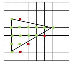
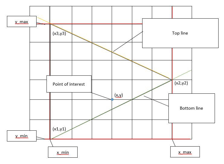
Determining if a point is valid
|
First, we need to know if the line we want to compare a coordinate to is the upper line of the triangle or the lower line of the triangle. To do this, we simply compare the y value of the coordinate of interest to the y2 value that was input. If the y value of interest is greater than the y2 value, then the line we want to compare to is the upper line. If it is equal to y2, we still compare it to the bottom line.
When comparing the current coordinates against the bottom line, x-x1 was stored into register A, y-y1 was stored into register B, x2-x1 was stored into register C0 and y2-y1 was stored into register D0. When comparing the current coordinates against the top line, x-x3 was stored into register A, y-y3 was stored into register B, x2-x3 was stored into register C1 and y2-y3 was stored into register D1. With these three things known (if it is an upper line, if the triangle is right facing or left facing, and the RLO result), we can tell if the point is valid or not. For bottom lines, if RLO is positive, the point is right of the line. For top lines, if RLO is negative, the point is to the right of the line. If RLO is zero, the point is on the line. |

|
Throughput of the system
The throughput for this design methodology is quite complicated to report. For every new row, B and BC values are calculated only once and there are different sizes/layouts of right and left-facing triangles. For right facing triangles there is one extra point analyzed which is not in the triangle boundary, whereas for left facing triangles all points inside a rectangle must be analyzed. The rectangle coordinates are
Case 1 - Left-facing triangle:
|
In this case, we waste clock cycles because we must start at x_min. We could generate an algorithm that calculates the first valid x coordinate, but that would be time consuming and make the design more complicated and area-consuming.
# of clock cycles to output complete = (x_1-x_2+1)×(y_3-y_1+1)×5+( y_3-y_1+1)×2+4 |
|
Case 2 - Right-facing triangle:
|
In this case, we can detect a “negative edge” of valid outputs and decide to move on to the next row in order to save some clock cycles.
# of clock cycles to output complete = (# of points in the triangle)×5+(y_3-y_1+1)×2+(y_3-y_1)×5+4 |

|
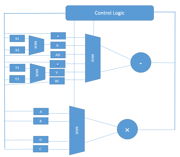
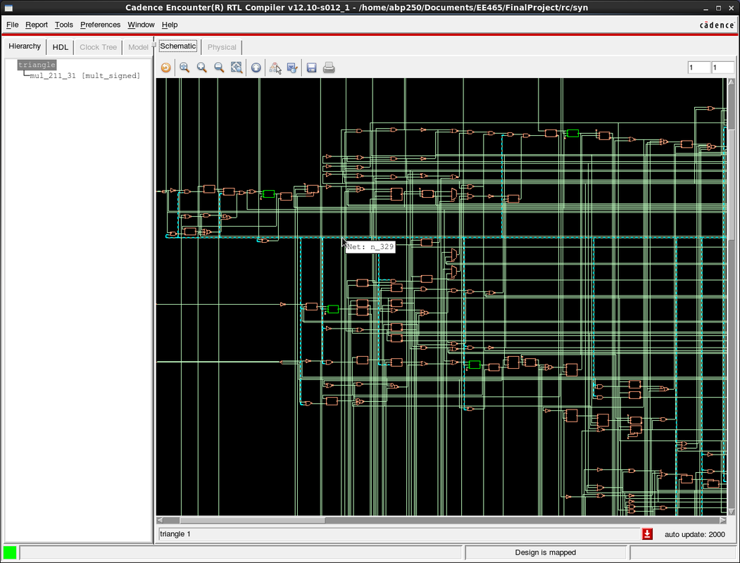
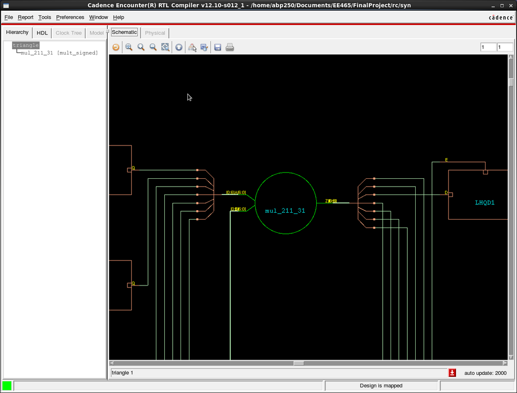
Device Sharing
Our main optimization goal of this project was to reduce area and power consumption by re-using devices. To do this, we decided to use only one multiplier and one adder as this is the minimum requirement for the computations. The thicker line is a bus which selects signals from the outputs of the multiplier or adder depending on which state the system is in. This is a rough diagram to show the basic idea of sharing the multiplier and adder.
Here is a top-level concept diagram of the sharing functionality of the design:
Here is a top-level concept diagram of the sharing functionality of the design:
Verilog Code
`timescale 100ps/10ps
module triangle(clk, reset, nt, xi, yi, busy, po, xo, yo);
input clk, reset, nt;
input [2:0] xi, yi;
output busy, po;
output [2:0] xo, yo;
wire clk, reset, nt;
wire [2:0] xi, yi;
reg [2:0] xo, yo, x_min, x_max, y_min, y_max, x, y;
reg [2:0] xi_ff[2:0], yi_ff[2:0];
reg busy, good, mul_en, sub_en, check, rst_int, inc_y, inc_x; //internal reset
reg po, po_, on_line, right_line , right_triangle, top_line; //right_triangle = 1 means right, 0 means left
reg signed [6:0] sub_ans , sub_op0, sub_op1, mul_op0, mul_op1;
reg signed [6:0] mul_ans, A, B, C0, D0, C1, D1, AD, BC, RLO;
reg [3:0] control, control_1;
always @ (posedge clk)begin
if(reset || rst_int) begin
xi_ff[0] <= 0;
xi_ff[1] <= 0;
xi_ff[2] <= 0;
yi_ff[0] <= 0;
yi_ff[1] <= 0;
yi_ff[2] <= 0;
x_min <= 7;
x_max <= 0;
y_min <= 7;
y_max <= 0;
//on_line <= 0;
//right_line <= 0;
top_line <= 0;
//right_triangle <= 0;
A <= 0;
B <= 0;
C0 <= 0;
C1 <= 0;
D0 <= 0;
D1 <= 0;
AD <= 0;
BC <= 0;
RLO <= 0;
control <= 0;
check <= 0;
//x <= 0;
//y <= 0;
xo <= 0;
yo <= 0;
busy <= 0;
//good <= 0;
//po <= 0;
//po_ <= 0;
rst_int <= 0;
inc_y <= 0;
inc_x <= 0;
end
else begin
if(control)begin
//control <= control_1;
if(control < 13)control <= control + 1;
else if(x == x_min) control <= 7;
else control <= 9;
end
else if(nt)begin
xi_ff[0] <= xi;
yi_ff[0] <= yi;
control <= 1;
end
if(control < 6)begin
if(xi > x_max) x_max <= xi;
if(xi < x_min) x_min <= xi;
if(yi > y_max) y_max <= yi;
if(yi < y_min) y_min <= yi;
end
else begin
if(y > yi_ff[1])top_line <= 1;
else top_line <= 0;
end
case(control)
1: begin
xi_ff[1] <= xi;
yi_ff[1] <= yi;
busy <= 1;
end
2: begin
xi_ff[2] <= xi;
yi_ff[2] <= yi;
end
3: begin
C0 <= sub_ans;
end
4: begin
D0 <= sub_ans;
end
5: begin
C1 <= sub_ans;
inc_y <= 1;
end
6: begin
D1 <= sub_ans;
inc_y <= 0;
end
7: begin //B = Y-Y1 B should be calculated first because it remains the same for all values on this row
//it will return here if there is a new row with a new y value
if(check)check <= 0;
B <= sub_ans;
if(inc_y)inc_y <= 0; //resets inc_y back to zero to prevent extra incramenting
if(inc_x)inc_x <= 0; //resets inc_x back to zero to prevent extra incramenting
end
8:begin //BC = B*C BC should be calculated first because it remains the same for all values on this row
BC <= mul_ans;
end
9: begin //A = X-X1 It will return here if it is just a new value of x
if(check)check <= 0;
A <= sub_ans;
if(inc_y)inc_y <= 0; //resets inc_y back to zero to prevent extra incramenting
if(inc_x)inc_x <= 0; //resets inc_x back to zero to prevent extra incramenting
end
10: begin
AD <= mul_ans;
end
11: begin //B = ans
RLO <= sub_ans;
end
12: begin
check <= 1; //check should be high for 2 clock cycles to pulse po and check for valid
xo <= x;
yo <= y;
end
13: begin
if(yo >= y_max)begin
if(right_triangle ^ (xo == x_max)) rst_int <= 1;
else if(xo == x_max) rst_int <= 1;
end
if((x == x_max) || ~good && right_triangle && ~inc_y) inc_y <= 1;
if((po_ || ~right_triangle) && ~inc_y) inc_x <= 1;
end
endcase
end//else begin
end//always @ (posedge clk)begin
always @(negedge clk) begin
if(inc_y)begin
if((control == 6)) y <= y_min;
else y <= y + 1;
x <= x_min;
end
else if(inc_x) x <= x + 1;
if(check)begin
if(good)begin
if(po)po<=0;
else begin
po <= 1;
po_ <= 1; // on the positive edge of po, po_ is set to 1
end
end//if(good)begin
else begin
po_ <= 0; // on the negative edge of po, po_ should be set to 0
end//else(~good)
end //if(check)begin
end //always @(negedge clk) begin
always@(posedge check)begin
if(((x == xi_ff[0]) && (y==yi_ff[0])) || ((x == xi_ff[1]) && (y == yi_ff[1])) || ((x == xi_ff[2]) && (y == yi_ff[2]))) good <= 1;
else if((right_triangle ~^ right_line) || on_line) good <= 1;
else good <= 0;
end
always @(*) begin //multiplier and adder modules
if(sub_en) sub_ans = sub_op0 - sub_op1;//multiplier block
if(mul_en) mul_ans = mul_op0 * mul_op1;//adder block
end
always @(*) begin
if(xi_ff[1]>xi_ff[0]) right_triangle = 1;
else right_triangle = 0;
end
always @(*) begin
if((RLO == 0) || (x == xi_ff[0]))begin
on_line = 1;
right_line = 0;
end
else begin
on_line = 0;
if(~top_line)right_line = RLO[6];
else right_line = ~RLO[6];
end
end
always @(*) begin //control logic
//if(control < 13) //determines next control
// control_1 = control + 1;
//else control_1 = 7;
case(control)
0: begin
end
1: begin
end
3: begin //C0 = X2-X1
sub_en = 1;
sub_op0 = xi_ff[1];
sub_op1 = xi_ff[0];
end
4: begin //D0 = Y2-Y1
sub_en = 1;
sub_op0 = yi_ff[1];
sub_op1 = yi_ff[0];
end
5:begin //C1 = x2-x3
sub_en = 1;
sub_op0 = xi_ff[1];
sub_op1 = xi_ff[2];
end
6: begin //D1 = Y2-Y3
sub_en = 1;
sub_op0 = yi_ff[1];
sub_op1 = yi_ff[2];
end
7: begin //B = Y-Y1
sub_en = 1;
mul_en = 0;
sub_op0 = y;
if(~top_line)sub_op1 = yi_ff[0];
else sub_op1 = yi_ff[2];
end
8: begin //BC = B*C
sub_en = 0;
mul_en = 1;
mul_op0 = B;
if(~top_line)mul_op1 = C0;
else mul_op1 = C1;
end
9: begin //A = X-X1
sub_en = 1;
mul_en = 0;
sub_op0 = x;
if(~top_line)sub_op1 = xi_ff[0];
else sub_op1 = xi_ff[2];
end
10: begin //AD = A*D
sub_en = 0;
mul_en = 1;
mul_op0 = A;
if(~top_line)mul_op1 = D0;
else mul_op1 = D1;
end
11: begin //RLO = AB-CD
mul_en = 0;
sub_en = 1;
sub_op0 = AD;
sub_op1 = BC;
end
12: begin
sub_en = 0;
mul_en = 0;
end
endcase
end
endmodule
Test-bench and Simulation
Test Bench File
Here is the test-bench which was provided with the contest files.
`timescale 100ps/10ps
`define CYCLE 100000 // Modify yo_tur clock period here (unit: 0.1ns)
`define INFILE1 "input.dat"
`define IN_LENGTH 6
`define INFILE2 "expect.dat"
`define OUT_LENGTH 48
`define SDF_FILE "triangle.sdf"
module triangle_tb;
parameter INPUT_DATA = `INFILE1;
parameter EXPECT_DATA = `INFILE2;
parameter period = `CYCLE * 10;
reg clk_t;
reg reset_t;
reg nt_t;
reg [2:0] xi_t, yi_t;
wire [2:0] xo_t, yo_t;
wire po_t;
wire busy_t;
integer i, j, k, l, out_f, err, pattern_num, total_num, total_cycle_num;
integer a, b, c, d;
reg [5:0] data_base [0:`IN_LENGTH - 1];
reg [5:0] data_base_expect [0:`OUT_LENGTH - 1];
reg [5:0] data_tmp_expect;
reg [5:0] data_tmp_i1, data_tmp_i2, data_tmp_i3;
triangle top(clk_t, reset_t, nt_t, xi_t, yi_t, busy_t, po_t, xo_t, yo_t);
//initial $sdf_annotate(`SDF_FILE,top);
initial $readmemb(INPUT_DATA, data_base);
initial $readmemb(EXPECT_DATA, data_base_expect);
initial begin
$dumpvars();
$dumpfile("triangle.vcd");
clk_t = 1'b1;
reset_t = 1'b0;
nt_t = 1'b0;
xi_t = 3'bz;
yi_t = 3'bz;
l = 0;
i = 0;
j = 0;
k = 0;
err = 0;
pattern_num = 1 ;
total_num = 0 ;
end
initial begin
out_f = $fopen("OUT.DAT");
if (out_f == 0) begin
$display("Output file open error !");
$finish;
end
end
always
#(period/2) clk_t = ~clk_t;
always
#(period*700) $stop;
initial begin
@(negedge clk_t)
reset_t = 1'b1;
$display ("\n****** START to VERIFY the Triangel Rendering Enginen OPERATION ******\n");
#(period - 0.1)
reset_t = 1'b0;
for(i = 0; i < `IN_LENGTH; i = i + k) begin
if(busy_t == 1'b1) begin
@(negedge clk_t)
nt_t =1'b0;
k =0;
end else begin
k = 3;
// cycle 1
@(negedge clk_t)
nt_t = 1'b1;
#(`CYCLE*3) // read x1 & y1
data_tmp_i1 = data_base[i];
xi_t = data_tmp_i1[5:3];
yi_t = data_tmp_i1[2:0];
@(posedge clk_t)
#(`CYCLE*2) // close x1 & y1
xi_t = 3'bz;
yi_t = 3'bz;
// cycle 2
@(negedge clk_t)
nt_t =1'b0;
#(`CYCLE*3) // read x2 & y2
data_tmp_i2 = data_base[i+1];
xi_t = data_tmp_i2[5:3];
yi_t = data_tmp_i2[2:0];
@(posedge clk_t)
#(`CYCLE*2) // close x2 & y2
xi_t = 3'bz;
yi_t = 3'bz;
// cycle 3
@(negedge clk_t)
#(`CYCLE*3) // read x3 & y3
data_tmp_i3 = data_base[i+2];
xi_t = data_tmp_i3[5:3];
yi_t = data_tmp_i3[2:0];
@(posedge clk_t)
#(`CYCLE*2) // close x3 & y3
xi_t = 3'bz;
yi_t = 3'bz;
$display("Waiting for the rendering operation of the triangle po_tint_ts with:");
$display("(x1, y1)=(%h, %h)",data_tmp_i1[5:3], data_tmp_i1[2:0]);
$display("(x2, y2)=(%h, %h)",data_tmp_i2[5:3], data_tmp_i2[2:0]);
$display("(x3, y3)=(%h, %h)",data_tmp_i3[5:3], data_tmp_i3[2:0]);
end
end
end
always @(posedge clk_t) begin
if (po_t ==1'b1) begin
data_tmp_expect = data_base_expect[l];
if ((xo_t !== data_tmp_expect[5:3])|| (yo_t!== data_tmp_expect[2:0])) begin
$display("ERROR at %d:xo_t=(%h) yo_t=(%h)!=expect xo_t=(%h), yo_t=(%h)",l
,xo_t, yo_t, data_tmp_expect[5:3], data_tmp_expect[2:0]);
err = err + 1 ;
end
$fdisplay(out_f,"%h%h",xo_t,yo_t);
l = l + 1;
end
if( l == `OUT_LENGTH ) begin
if (err == 0)
$display("PASS! All data have been generated successfully!");
else begin
$display("---------------------------------------------");
$display("There are %d errors!", err);
$display("---------------------------------------------");
end
$display("---------------------------------------------");
total_num = total_cycle_num * period;
$display("Total delay: %d ns", total_num );
$display("---------------------------------------------");
$stop;
end
end
always @(posedge clk_t) begin
if (reset_t == 1'b1)
total_cycle_num = 0 ;
else
total_cycle_num = total_cycle_num + 1 ;
end
endmodule
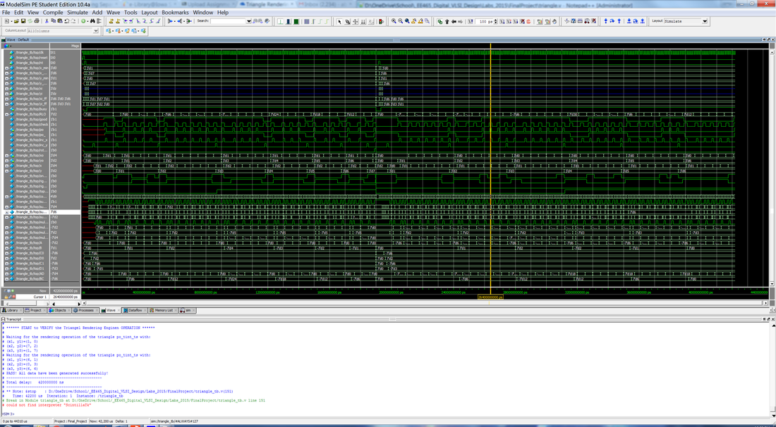
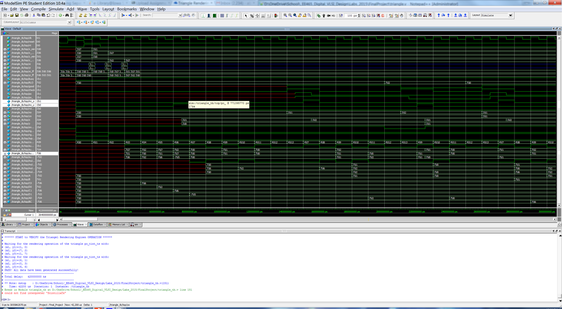
Simulation
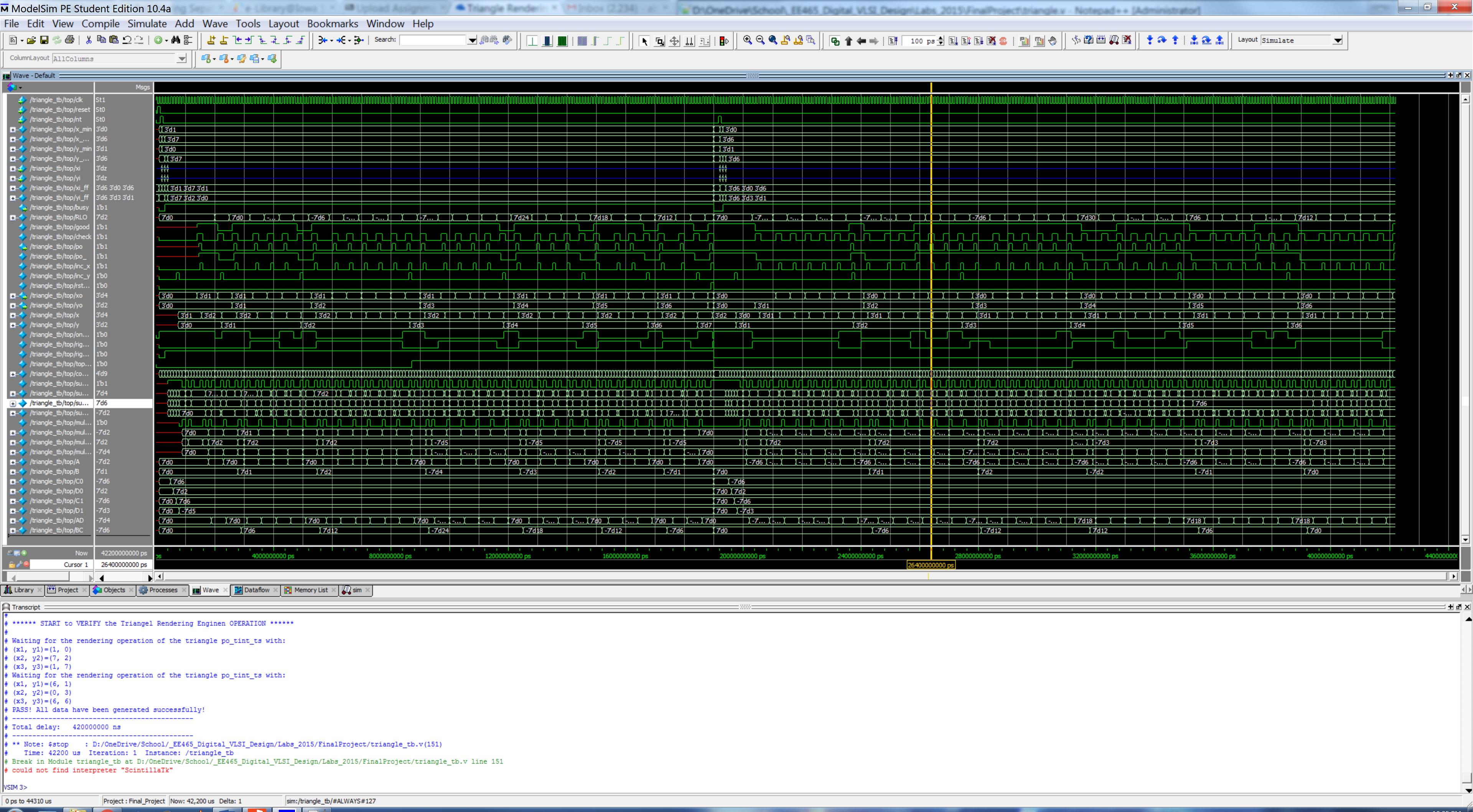
After compiling the code above and running it, we get the following output waveform:

As you can see, the module has passed the testbench. This means our design works and we can begin the synthesis to layout process.
| tre_modelsim1.png |
RTL Synthesis
Cadence RTL Synthesizer(rc) was used to perform RTL (Register Transfer Level) synthesis. The first attempts at RTL synthesis were unsuccessful and gave multiple driver warnings. Those warnings came from setting register values under different always blocks in the Verilog code. When the synthesizer sees multiple drivers, it just assigns the register a value. Sometimes it assigns the register to be both high and low at the same time, which means that the register output is connected to both power and ground. Those problems were fixed by re-writing the Verilog code so that values were only being set under one always block.
The timing report had to be verified for a positive slack time after running synthesis. If the slack time was negative in synthesis, then it would definitely be negative in layout. A negative slack time means that a signal arrives at an input later than it needs to in order for the functionality to remain the same. A positive slack time means that the signal arrived at an input early. The goal is to get the slack time as close to zero as possible to reduce wasted power, area, and clock cycles.
We used the following script to synthesize our design with a clock period constraint of 400 ns and leakage power constraints:
## This sets the name of the directory in which area/timing/power reports
## and synthesized (mapped) netlists are stored.
set OUTPUT_DIR ./run_dir
if { ![file exists ${OUTPUT_DIR}] } { sh mkdir ${OUTPUT_DIR} }
#### Step 1 ####
## This tells the compiler where to look for the libraries
set_attribute lib_search_path ../libdir
## This defines the libraries to use
set_attribute library {tcbn65gpluswc.lib}
#### Step 2 ####
##This must point to your VHDL/verilog file
load -v2001 ../../triangle.v
set_attribute lp_insert_clock_gating true
#### Step 3 ####
## This builds the general block
elaborate
read_sdc ./scripts/design.sdc
dc::set_time_unit -picoseconds
dc::set_load_unit -picofarads
define_clock -period 400 -name clk [dc::get_ports {clk}] -rise 10 -fall 10
set_attribute lp_power_unit {nW}
set_attribute max_leakage_power 10000 /designs/triangle
set_attribute power_optimization_effort high
synthesize -to_mapped -effort high
report area > ${OUTPUT_DIR}/area.rpt
report gates > ${OUTPUT_DIR}/gates.rpt
report timing > ${OUTPUT_DIR}/timing.rpt
report timing -lint > ${OUTPUT_DIR}/lint.rpt
report summary > ${OUTPUT_DIR}/summary.rpt
report power > ${OUTPUT_DIR}/power.rpt
report clock_gating -summary > ${OUTPUT_DIR}/clk_gating.rpt
write -mapped > ${OUTPUT_DIR}/design_mapped.v
write_script > ${OUTPUT_DIR}/design_mapped.g
write_sdc > ${OUTPUT_DIR}/design_mapped.sdc
The synthesis ran smoothly and we got the following reports. Note that we intend to run the design with a clock period of 500ns, so even if there is a slight timing violation for this synthesis, we will still have a robust design.
Area report============================================================
Generated by: Encounter(R) RTL Compiler v12.10-s012_1
Generated on: Dec 10 2015 08:44:21 pm
Module: triangle
Technology library: tcbn65gpluswc 121
Operating conditions: WCCOM (balanced_tree)
Wireload mode: segmented
Area mode: timing library
============================================================
Instance Cells Cell Area Net Area Total Area Wireload
-----------------------------------------------------------------------------
triangle 577 2131 0 2131 ZeroWireload (S)
mul_211_31 74 199 0 199 ZeroWireload (S)
RC_CG_HIER_INST19 1 7 0 7 ZeroWireload (S)
RC_CG_HIER_INST18 1 7 0 7 ZeroWireload (S)
RC_CG_HIER_INST9 1 6 0 6 ZeroWireload (S)
RC_CG_HIER_INST8 1 6 0 6 ZeroWireload (S)
RC_CG_HIER_INST7 1 6 0 6 ZeroWireload (S)
RC_CG_HIER_INST6 1 6 0 6 ZeroWireload (S)
RC_CG_HIER_INST5 1 6 0 6 ZeroWireload (S)
RC_CG_HIER_INST4 1 6 0 6 ZeroWireload (S)
RC_CG_HIER_INST3 1 6 0 6 ZeroWireload (S)
RC_CG_HIER_INST2 1 6 0 6 ZeroWireload (S)
RC_CG_HIER_INST17 1 6 0 6 ZeroWireload (S)
RC_CG_HIER_INST16 1 6 0 6 ZeroWireload (S)
RC_CG_HIER_INST15 1 6 0 6 ZeroWireload (S)
RC_CG_HIER_INST14 1 6 0 6 ZeroWireload (S)
RC_CG_HIER_INST13 1 6 0 6 ZeroWireload (S)
RC_CG_HIER_INST12 1 6 0 6 ZeroWireload (S)
RC_CG_HIER_INST11 1 6 0 6 ZeroWireload (S)
RC_CG_HIER_INST10 1 6 0 6 ZeroWireload (S)
RC_CG_HIER_INST1 1 6 0 6 ZeroWireload (S)
RC_CG_HIER_INST0 1 6 0 6 ZeroWireload (S)
(S) = wireload was automatically selected
|
Power Report============================================================
Generated by: Encounter(R) RTL Compiler v12.10-s012_1
Generated on: Dec 10 2015 08:44:21 pm
Module: triangle
Technology library: tcbn65gpluswc 121
Operating conditions: WCCOM (balanced_tree)
Wireload mode: segmented
Area mode: timing library
============================================================
Leakage Dynamic Total
Instance Cells Power(nW) Power(nW) Power(nW)
----------------------------------------------------------
triangle 577 13865.421 639936.468 653801.889
mul_211_31 74 975.410 0.000 975.410
RC_CG_HIER_INST18 1 44.154 11500.000 11544.154
RC_CG_HIER_INST19 1 44.154 11500.000 11544.154
RC_CG_HIER_INST14 1 42.210 12274.479 12316.689
RC_CG_HIER_INST16 1 42.196 12398.698 12440.893
RC_CG_HIER_INST10 1 41.953 13730.599 13772.552
RC_CG_HIER_INST13 1 41.953 13730.599 13772.552
RC_CG_HIER_INST0 1 41.591 14379.297 14420.888
RC_CG_HIER_INST1 1 41.591 14379.297 14420.888
RC_CG_HIER_INST11 1 41.591 14379.297 14420.888
RC_CG_HIER_INST12 1 41.591 14379.297 14420.888
RC_CG_HIER_INST15 1 41.591 14379.297 14420.888
RC_CG_HIER_INST17 1 41.591 14379.297 14420.888
RC_CG_HIER_INST2 1 41.591 14379.297 14420.888
RC_CG_HIER_INST3 1 41.591 14379.297 14420.888
RC_CG_HIER_INST4 1 41.591 14379.297 14420.888
RC_CG_HIER_INST5 1 41.591 14379.297 14420.888
RC_CG_HIER_INST6 1 41.591 14379.297 14420.888
RC_CG_HIER_INST7 1 41.591 14379.297 14420.888
RC_CG_HIER_INST8 1 41.591 14379.297 14420.888
RC_CG_HIER_INST9 1 41.591 14379.297 14420.888
|
Timing Report============================================================
Generated by: Encounter(R) RTL Compiler v12.10-s012_1
Generated on: Dec 10 2015 08:44:21 pm
Module: triangle
Technology library: tcbn65gpluswc 121
Operating conditions: WCCOM (balanced_tree)
Wireload mode: segmented
Area mode: timing library
============================================================
Pin Type Fanout Load Slew Delay Arrival
(fF) (ps) (ps) (ps)
----------------------------------------------------------------
(clock clk) launch 40 R
x_max_reg[0]/CP 0 40 R
x_max_reg[0]/Q DFQD4 4 4.3 27 +111 151 R
g11669/A1 +0 151
g11669/ZN IND2D1 2 2.7 38 +50 201 R
g4936/A1 +0 201
g4936/ZN NR2XD0 1 1.2 32 +27 228 F
g4920/A1 +0 228
g4920/ZN NR2D1 1 2.0 55 +42 270 R
g4908/B +0 270
g4908/ZN AOI211XD1 1 0.8 40 +36 306 F
g4905/A1 +0 306
g4905/ZN NR2D0 1 1.0 64 +50 356 R
g4900/A1 +0 356
g4900/ZN NR2XD0 1 1.0 34 +32 388 F
RC_CG_HIER_INST14/enable
RC_CGIC_INST/E CKLNQD1 +0 388
RC_CGIC_INST/CP setup 0 +51 439 R
- - - - - - - - - - - - - - - - - - - - - - - - - - - - - - - -
(clock clk) capture 440 R
----------------------------------------------------------------
Cost Group : 'cg_enable_group_clk' (path_group 'cg_enable_group_clk')
Timing slack : 1ps
Start-point : x_max_reg[0]/CP
End-point : RC_CG_HIER_INST14/RC_CGIC_INST/E
|
Clock Gating Report============================================================
Generated by: Encounter(R) RTL Compiler v12.10-s012_1
Generated on: Dec 10 2015 08:44:21 pm
Module: triangle
Technology library: tcbn65gpluswc 121
Operating conditions: WCCOM (balanced_tree)
Wireload mode: segmented
Area mode: timing library
============================================================
-----------------------------------------------------------------------
Category Number % Average Toggle Saving %
-----------------------------------------------------------------------
RC Clock Gating Instances 20 100 100.00
Non-RC Clock Gating Instances 0 0 0.00
-----------------------------------------------------------------------
RC Gated Flip-flops 110 93 100.00
Non-RC Gated Flip-flops 0 0 0.00
-----------------------------------------------------------------------
Total Ungated Flip-Flops 8 7 -
Register bank width too small 8 100 -
-----------------------------------------------------------------------
Total Flip-Flops 118 - -
-----------------------------------------------------------------------
|
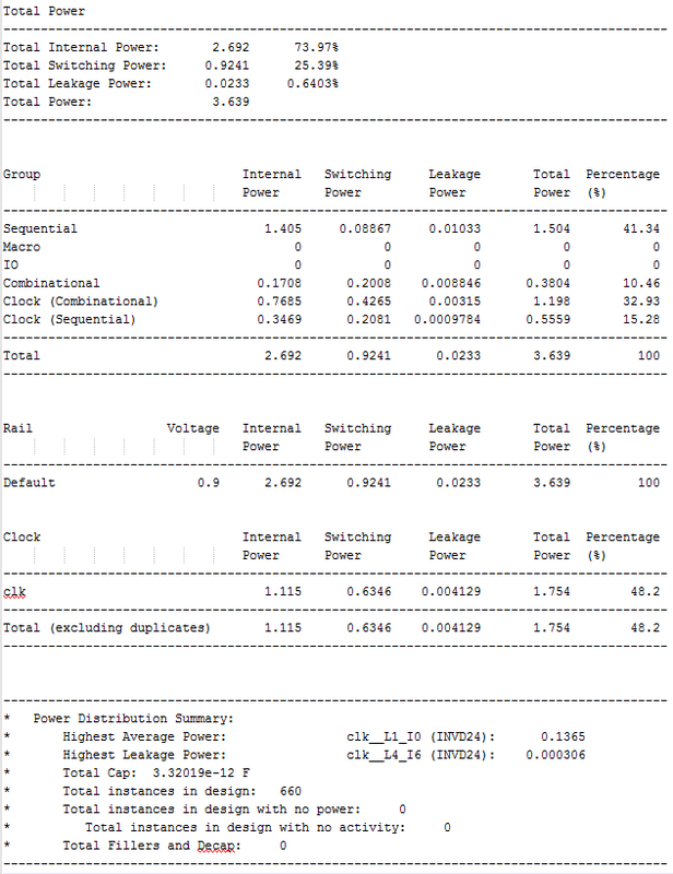
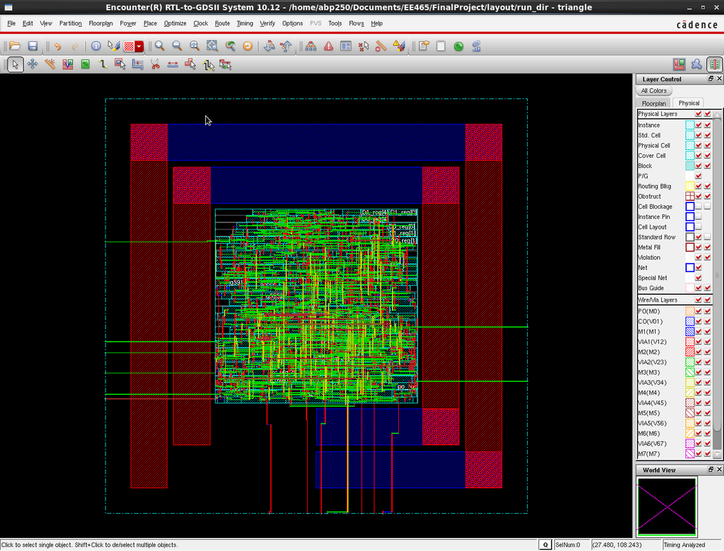
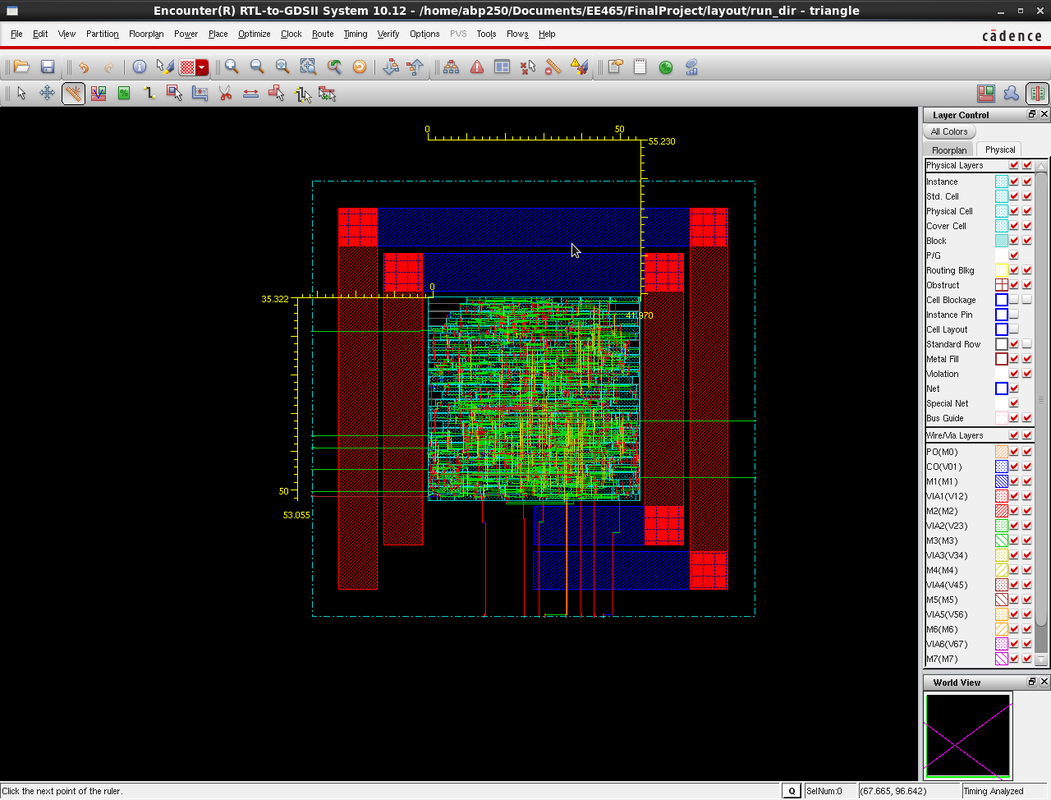
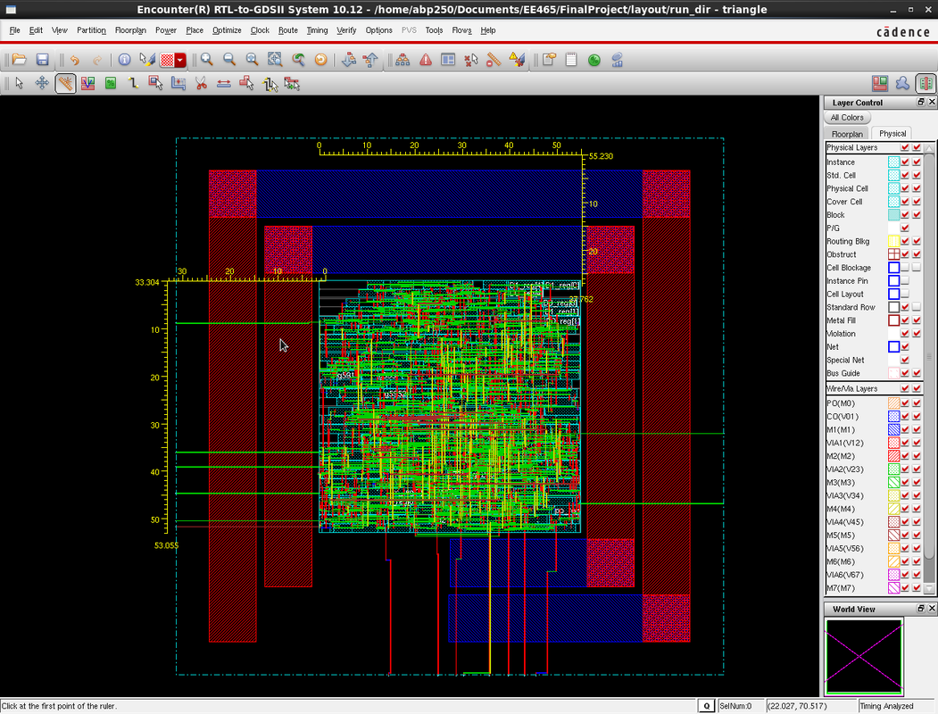
Layout
Cadence Encounter was used to perform the layout of the Triangle Rendering Engine following the encounter instructions given below.
| encounter-instructions.pdf |
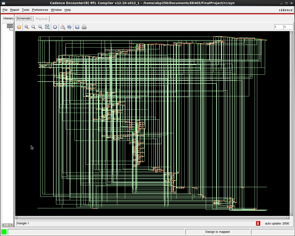
The result of our layout synthesis is below:
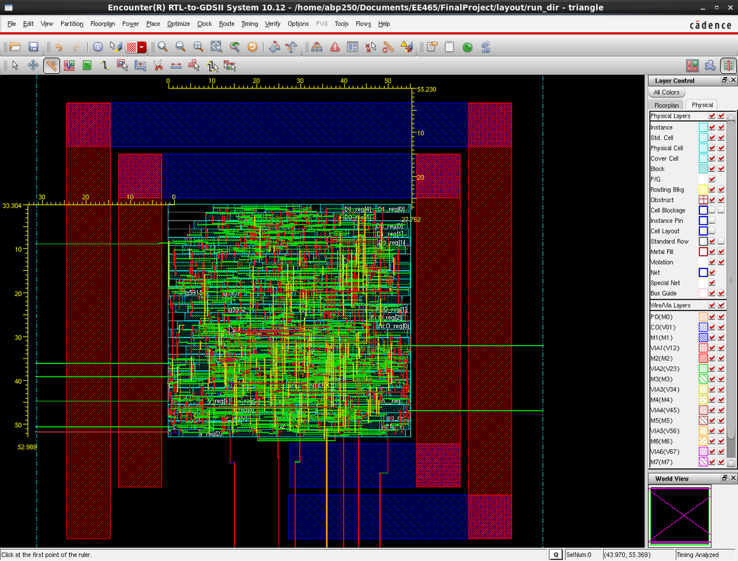
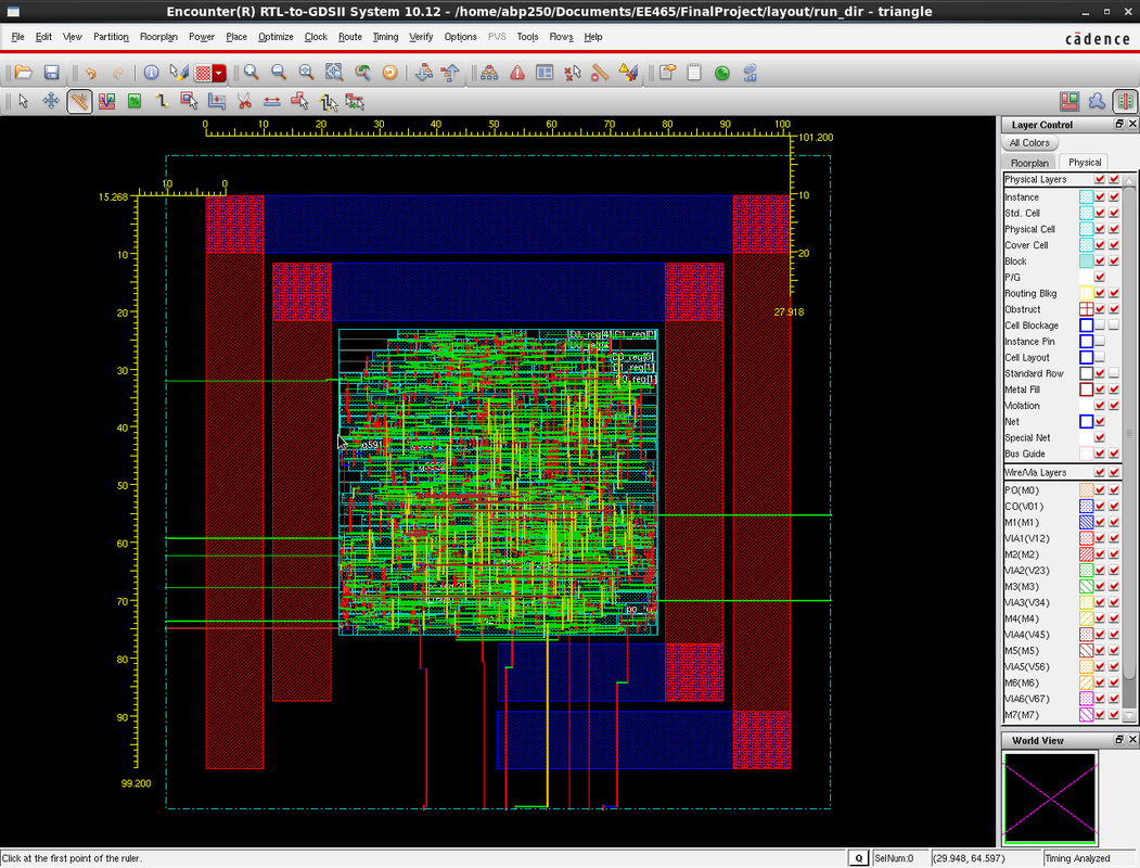
Using the measurement tool in encounter, we measured the final area of our IC to be 0.002927 µm^2. Again, we synthesized it so the clock period constraint was 0.400 ns so we got a total slack of -.071 ns but run at .500 ns, we would have a slack of 0.029 ns. Total Power Consumption was 3.639 mW.
Layout Timing Report
###############################################################
# Generated by: Cadence Encounter 10.12-s181_1
# OS: Linux x86_64(Host ID co2046-06.ece.iastate.edu)
# Generated on: Thu Dec 10 21:11:50 2015
# Design: triangle
# Command: report_timing > timing.rpt
###############################################################
Path 1: VIOLATED Clock Gating Setup Check with Pin RC_CG_HIER_INST17/RC_CGIC_
INST/CP
Endpoint: RC_CG_HIER_INST17/RC_CGIC_INST/E (v) checked with leading edge of
'clk'
Beginpoint: y_min_reg[1]/Q (v) triggered by leading edge of
'clk'
Other End Arrival Time 0.137
- Clock Gating Setup 0.048
+ Phase Shift 0.400
= Required Time 0.490
- Arrival Time 0.561
= Slack Time -0.071
Clock Rise Edge 0.040
+ Clock Network Latency (Prop) 0.178
= Beginpoint Arrival Time 0.218
+-------------------------------------------------------------------------------------------+
| Instance | Arc | Cell | Delay | Arrival | Required |
| | | | | Time | Time |
|--------------------------------+--------------+--------------+-------+---------+----------|
| y_min_reg[1] | CP ^ | | | 0.218 | 0.147 |
| y_min_reg[1] | CP ^ -> Q v | DFQD4 | 0.143 | 0.361 | 0.290 |
| g7363 | A2 v -> ZN ^ | OAI211D2 | 0.037 | 0.398 | 0.327 |
| g7362 | A1 ^ -> ZN v | ND2D1 | 0.040 | 0.438 | 0.367 |
| g7361 | A v -> CON ^ | FCICOND1 | 0.073 | 0.511 | 0.440 |
| g5975 | A2 ^ -> ZN v | OAI21D2 | 0.049 | 0.561 | 0.490 |
| RC_CG_HIER_INST17 | enable v | RC_CG_MOD_17 | | 0.561 | 0.490 |
| RC_CG_HIER_INST17/RC_CGIC_INST | E v | CKLNQD1 | 0.000 | 0.561 | 0.490 |
+-------------------------------------------------------------------------------------------+
Layout Power Report
Gallery


Lab Documents
| triangle.zip |
| tre_final_report.pdf |
